Table of Contents
What IIC and STC Actually Measure
- STC (Sound Transmission Class): Lab-Measured Resistance to Airborne Sound Through a Wall, Floor, Door, or Window Assembly
- IIC (Impact Insulation Class): Lab-Measured Resistance to Impact Sound Through a Floor-Ceiling Assembly
- ASTC (Apparent STC): The Field-Measured Equivalent of STC — Includes Flanking and Real Construction Conditions
- AIIC (Apparent IIC): The Field-Measured Equivalent of IIC
- Field Penalty: ASTC and AIIC Typically Test 3 to 5 Points Lower Than the Lab STC and IIC of the Same Assembly
STC and IIC are the two ratings that govern almost every multi-family and hotel acoustic specification in the United States. STC handles airborne sound — voices, music, television, HVAC noise, anything that travels through the air. IIC handles impact sound — footfall, dropped objects, furniture moving, anything that strikes the floor structure directly, which is why an IIC 45 floor system can make or break a multi-level build.
Both ratings come from controlled laboratory tests. Real construction in real buildings always performs a few points lower because lab tests isolate the assembly from flanking paths (the routes sound takes around the wall through the structure, doors, penetrations, and shared cavities). When designers spec STC 50 on a wall schedule, they should be reading that as a target of ASTC 45 to 47 in the field.
The deeper background on the difference between airborne and impact noise lives in our airborne vs structure-borne noise guide.
STC Rating Chart by Building Element
The STC rating you should target depends on which building element you are specifying and what use class the space falls under. Walls between dwelling units have a different floor than interior partitions inside the same unit. Exterior windows facing a busy street have a different floor than interior doors. The chart below maps the working windows for the most common elements.
| Element | Code Minimum | Typical Range | High-End Target |
|---|---|---|---|
| Demising Wall (Unit-to-Unit) | STC 50 (IBC 1207.1) | STC 50 to 56 | STC 60+ (luxury condo) |
| Corridor-to-Unit Wall | STC 50 (IBC 1207.1) | STC 50 to 56 | STC 60+ |
| Interior Partition (Same Unit) | No code minimum | STC 35 to 45 | STC 50 |
| Standard Solid Core Door | No code minimum | STC 24 to 32 | STC 40+ (acoustic door) |
| Single-Pane Window | No code minimum | STC 26 to 32 | STC 38+ (laminated) |
| Double-Pane Window | No code minimum | STC 32 to 38 | STC 45+ (laminated dual-pane) |
The door and window rows are where most code-compliant walls fail in the field. A wall rated at STC 50 with a door rated at STC 24 in the same partition delivers an effective STC closer to 28 because the door becomes the dominant flanking path. Door and window STC has to be specified in conjunction with the surrounding wall STC, not independently.
IIC Rating Chart for Floor Assemblies
IIC rating depends on the floor assembly type and the finished floor material. Concrete floor assemblies generally outperform wood-frame assemblies on impact insulation. Carpet over pad nearly always tests higher than hardwood, LVT, or tile because soft finished floors absorb impact at the source.
| Floor Assembly | Finished Floor | Typical IIC | With Underlayment |
|---|---|---|---|
| 6″ Concrete Slab | Bare Concrete | IIC 25 to 30 | N/A |
| 6″ Concrete Slab | LVT (Floating) | IIC 50 to 56 | IIC 56 to 60+ |
| 6″ Concrete Slab | Carpet + Pad | IIC 65 to 75+ | IIC 70+ |
| Wood-Truss Floor | LVT (Floating) | IIC 50 to 55 | IIC 55 to 62 |
| Wood-Truss Floor | Hardwood (Nailed) | IIC 35 to 45 | IIC 50 to 54 |
The underlayment column is where most condo flooring permit applications get won or lost. A bare concrete slab alone almost never meets the IIC 50 code minimum. Adding a rated acoustic underlayment under any finished floor brings the assembly into the compliant range. The product line that handles this lives at the Floor Blokker acoustic underlayment page.
IBC Code Minimums and Brand Standards
- IBC Section 1207.1: STC 50 (Lab) for Walls Between Dwelling Units
- IBC Section 1207.2: IIC 50 (Lab) for Floor-Ceiling Assemblies Between Dwelling Units
- Field Equivalent (Approximation): ASTC 45 and AIIC 45 in the Built Assembly
- Hotel Brand Standard: STC 55 to 60 — Marriott, Hilton, Hyatt, IHG All Spec Above Code
- Luxury Condo Standard: STC 55 to 60+ Driven by Buyer Expectation, Not Code
The International Building Code Section 1207 establishes the floor for residential acoustic separation in the United States. Almost every state and municipality adopts IBC 1207 either by reference or with minor amendments. The Florida Building Code adopts IBC 1207 directly for multi-family construction. Most jurisdictions enforce STC 50 lab-tested as the minimum for walls between dwelling units and IIC 50 for floor-ceiling assemblies between dwelling units.
Hotels and luxury condos almost always exceed code by 5 to 10 STC points because the brand standard or buyer expectation is higher than the legal minimum. A code-compliant STC 50 wall is fine for a budget apartment but reads as cheap construction in a luxury condo where buyers expect to hear effectively nothing from neighboring units.
South Florida Flooring Soundproofing Permit Guides
Every South Florida city runs its own flooring permit process, and the documentation that clears plan review in one jurisdiction does not always clear it in the next. The guides below break down what each building department asks for, the STC and IIC values the inspector wants on paper, and the floor assemblies that pass the first time. Pick your city.
Hallandale Beach: Condo Flooring Permit STC and IIC 50 Compliance
- Target Ratings: STC 50 and IIC 50, Lab-Tested
- Permit Trigger: Carpet Replaced with LVT, Hardwood, or Tile
- Required Documentation: Manufacturer Spec Sheets for the Floor Assembly
Hallandale Beach enforces STC 50 and IIC 50 at the city permit level, triggered the moment an owner pulls carpet and installs LVT, hardwood, or tile. The guide covers the manufacturer spec sheets the permit office accepts and the underlayment-plus-finish combinations that hit the rating on concrete and wood-truss subfloors.
Fort Lauderdale: Hard-Surface Flooring Permit Requirements
- Jurisdiction: City of Fort Lauderdale, Broward County
- Code Basis: Florida Building Code STC 50 / IIC 50 Baseline
- Submittal: Floating Floor Assembly Documentation Package
Fort Lauderdale sits in Broward County and holds hard-surface condo floors to the STC 50 and IIC 50 baseline written into the Florida Building Code. The guide details the submittal package the building department expects and how to document a floating floor assembly before the inspector signs off on the conversion.
Miami: Apartment and Condo Flooring Acoustic Permits
- Review Authority: Miami-Dade Building Department
- Highest Scrutiny: Carpet-to-Hard-Surface Multifamily Conversions
- Pass Path: Underlayment Rated for Tile and Engineered Wood
Miami flooring permits run through Miami-Dade review, where carpet-to-hard-surface conversions in multifamily buildings draw the most scrutiny. The guide lays out the acoustic documentation Miami plan reviewers request, the STC and IIC targets they check against, and the underlayments that carry the rating across tile and engineered wood.
Miami Beach: High-Rise Condo Flooring Permit Standards
- Building Stock: High-Rise Condo Towers with Stacked Units
- Standard: Flooring Permit Tied to Building Acoustic Rules
- Extra Layer: HOA Requirements Often Exceed the City Minimum
Miami Beach leans heavily on high-rise condo stock, where impact noise between stacked units is a constant complaint. The guide explains how the city ties flooring permits to acoustic standards, what the HOA usually layers on top, and the assemblies that satisfy both the inspector and the unit below.
What IIC and STC Should a Condo Target?
The right STC and IIC target for a condo depends on the building class, the buyer expectation, and the local code. Code-minimum apartments and entry-level condos hit STC 50 / IIC 50 lab-tested. Luxury condos run higher because buyers compare units against quiet single-family experience.
| Condo Class | Wall STC Target | Floor IIC Target | Notes |
|---|---|---|---|
| Code-Minimum / Entry-Level | STC 50 | IIC 50 | IBC 1207.1 / 1207.2 baseline |
| Mid-Market Condo | STC 52 to 55 | STC 52 to 55 | Reduces complaint volume meaningfully |
| Luxury Condo | STC 55 to 60+ | IIC 55 to 60+ | Buyer expectation, not code |
| Ultra-Luxury / Penthouse | STC 60+ | IIC 65+ | Effectively silent neighbor performance |
The middle two rows are where most condo developers land. Code-minimum is legal but generates complaint volume. Ultra-luxury adds cost that most buildings cannot recover. Mid-market and luxury (STC 52 to 60) is the right band for almost any condo project that wants to keep complaints below the threshold where the HOA gets involved.
Field Findings: Why Real Walls Underperform Lab Specs
Field findings from a Central Florida apartment complex acoustic review (2017) make the lab-versus-field gap concrete. An architecture firm asked for an audit on standard wall details that had been spec’d at STC 50+ but were generating noise complaints in the built units. Figures 1 and 2 below show the wall schedule details for the two assembly types tested. The wall STC reference assemblies appear in Figures 8, 9, and 10 at the bottom of this page.
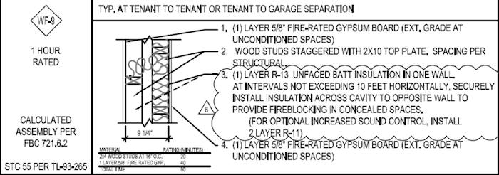
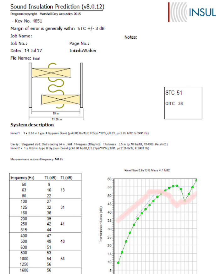
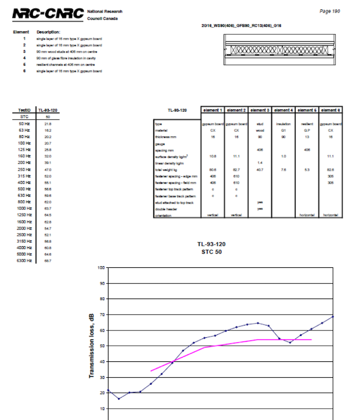
WF-9 Tenant-to-Tenant Double-Stud Wall
- Stud Configuration: Two Sets of 2×4 Studs With a Shared 10-Inch Top Plate
- Spec’d Lab STC: 55
- Built STC (With Top Plate): 51
- Field ASTC: 50 (Above Florida Building Code Minimum)
- Flanking at Wall Base: 3 to 5 dB
The shared top plate diminished the wall’s lab STC of 55 to a built STC of 51 because it allowed direct propagation through the top plate. Adding a thin bead of acoustic sealant along the wall base would have lifted the field STC by several more points. The WF-9 ASTC test data is shown in Figure 3, and the top-plate effect on the assembly’s STC is illustrated in Figures 8 and 9 at the bottom of this page.
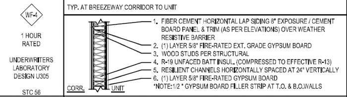
WF-4 Breezeway Corridor-to-Unit Wall (Kitchen)
- Decoupling: Resilient Channel
- Compromise: Wood Blocking Added to Support Kitchen Cabinets
- Wall Schedule STC: 56 (No Acoustic Test Number Referenced)
- Tested STC With Blocking: 50
- Door STC: 24 (Dominant Flanking Path)
- Effective STC at Door Zone: ~28
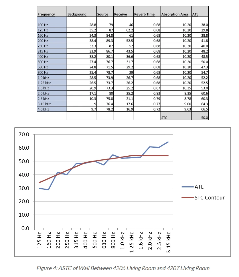
The blocking screws penetrated through the drywall into the studs, defeating the resilient channel decoupling. The kitchen door was the dominant flanking path: an STC 24 door in an STC 50 wall delivered effective STC closer to 28 in the door zone. The WF-4 Kitchen ASTC test data is shown in Figure 4, and the calculated STC for this assembly with blocking is shown in Figure 10 at the bottom of this page.
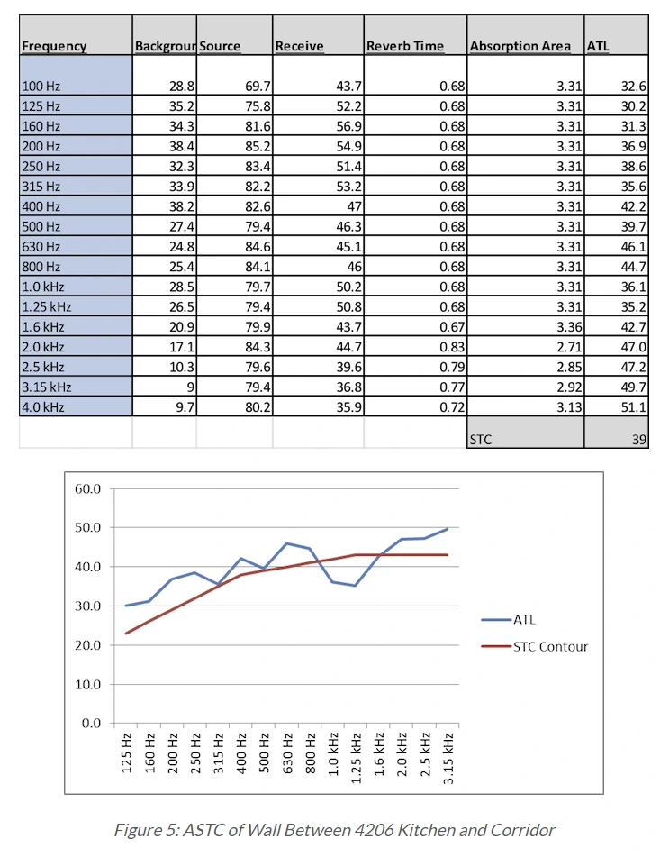
WF-4 Breezeway Corridor-to-Unit Wall (Closet)
- Wall Type: Same as WF-4 Kitchen
- Wood Blocking: Less (Lighter Shelves)
- Field ASTC: 43 (Slightly Below Florida Building Code)
- Implication: Even Reduced Blocking Affects Resilient Channel Performance
Same wall type as the kitchen test, with less wood blocking, but the field result still came in below code. Demonstrated that even small mechanical bridges through a resilient channel system meaningfully drop the assembly below the Florida Building Code minimum. The WF-4 Closet ASTC test data is shown in Figure 5.
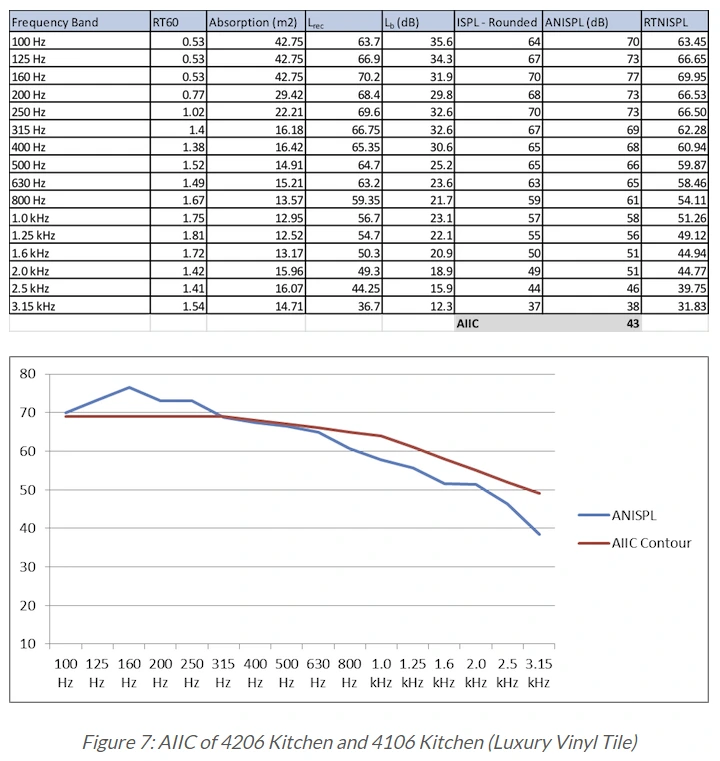
Test 4: Kitchen Flooring (FC-1) — AIIC 43
- Finished Floor: 20mm Wear-Layer LVT
- Substrate: 3/4″ Gypcrete, AccuQuiet D18 Underlayment, 3/4″ OSB
- Truss + Ceiling: 20″ Wood Floor Truss, R-13 Batt, Resiliently Mounted 5/8″ Type X Drywall
- Field AIIC: 43 (Below Florida Building Code Minimum)
- Issue 1: Underlayment Only Under LVT Section (Flanking Around Perimeter)
- Issue 2: Floor Perimeter Isolation Strips Only in Kitchen (Additional Flanking)
The Gypcrete moves footfall energy laterally around the underlayment into the OSB subfloor, bypassing the acoustic isolation. The AccuQuiet D18 underlayment spec (Figure 6b) also raised a documentation concern: the construction and referenced assemblies sheet listed no Acoustic Test number for the floor system, and the manufacturer’s literature claimed 6 to 12 IIC points of improvement without providing a third-party test report. As a rule, IIC and STC ratings on floor schedules should have an accompanying lab test reference available in the design package. AIIC test data for this floor is shown in Figure 6a.

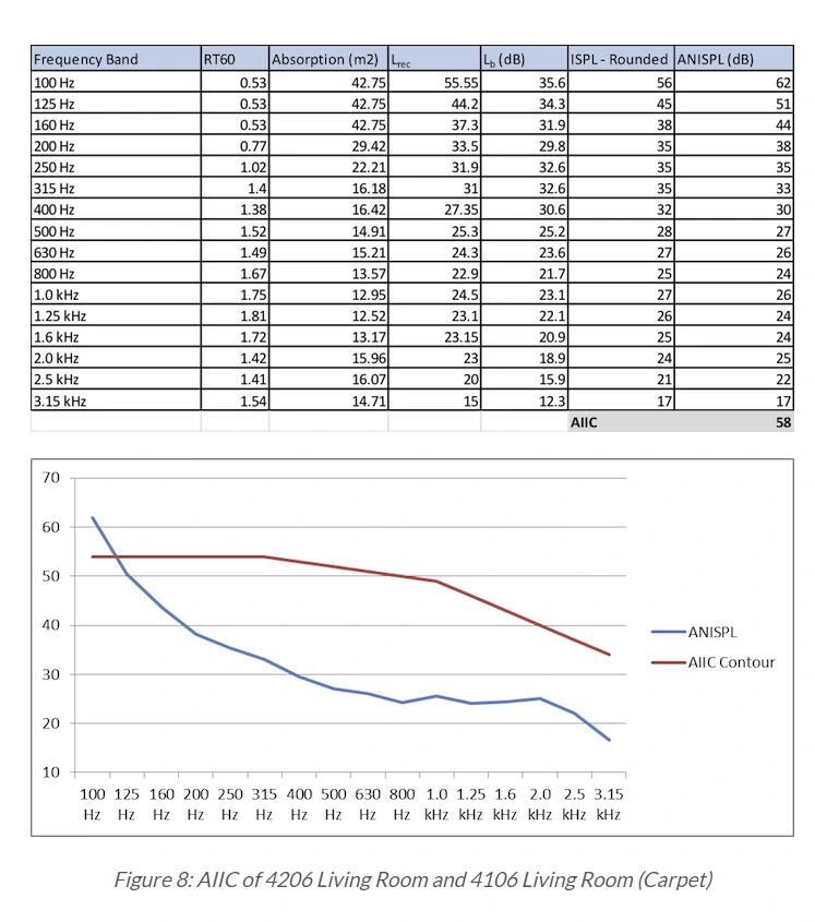
Test 5: Living Room Flooring (FC-1) — AIIC 58
- Floor Assembly: Same as Test 4
- Finished Floor: Carpet and Pad (Instead of LVT)
- Field AIIC: 58 (Well Above Florida Building Code)
- IIC Swing vs LVT: ~15 Points
- Implication: Carpet-to-Hard-Surface Replacement Is the Largest Acoustic Decision in a Condo
This is the single largest acoustic difference any finished-floor decision can make and the reason condo flooring permits in many jurisdictions trigger documentation requirements specifically when carpet is being replaced with a hard surface. AIIC test data is shown in Figure 7.
Common Causes of STC and IIC Loss
- Shared Top Plate or Bottom Plate: Direct Path Around Decoupled Studs (Drops STC 3 to 5 Points)
- Wood Blocking Through Resilient Channel: Fasteners Bridge the Decoupling, Defeating the Channel Benefit
- Standard Solid Core Doors in High-STC Walls: STC 24 Door in STC 50 Wall Delivers Effective STC ~28 in the Door Zone
- Penetrations Without Acoustic Sealant: Outlets, Conduit, HVAC Boots — All Flanking Paths
- Missing Bead at Wall Base: Floor-to-Wall Joint Leaks Without Acoustic Caulk
- Underlayment Adhered Down When Floating Was Spec’d: Loses 3 to 5 IIC Points
The pattern across these failure modes is the same: the lab STC of an isolated assembly is the upper bound. Anything that creates a coupling path, a flanking path, or a leak between source and receiver pulls the field result down toward that path’s transmission characteristic. A wall is only as good as its weakest acoustic element.
For deeper coverage on how vibration and structure-borne paths move through real building assemblies, see our how vibration travels through buildings guide.
Conclusion: Designing for STC and IIC Compliance
STC and IIC compliance is a design problem, a construction problem, and a documentation problem. Spec the lab values 5 points above the field target. Construct the assembly without bridging the decoupling layers. Document the resulting performance with manufacturer spec sheets or field tests when the jurisdiction requires it. Skipping any of those three steps produces complaints, permit denials, or HOA disputes — usually all three. Contact Us for an STC and IIC review on a specific project or permit application.
FAQs: IIC and STC Ratings
What is the difference between IIC and STC?
STC measures resistance to airborne sound (voices, music, HVAC) through a wall, floor, door, or window. IIC measures resistance to impact sound (footfall, dropped objects) through a floor-ceiling assembly. Walls use STC. Floors use both – STC for airborne and IIC for impact.
What is a good IIC and STC rating for a condo?
Code minimum is STC 50 / IIC 50 lab-tested per IBC 1207. Mid-market condos target STC 52 to 55. Luxury condos target STC 55 to 60+. Many South Florida jurisdictions enforce STC 50 / IIC 50 at the permit level for condo flooring replacements.
Why does the field STC come in lower than the lab STC?
Lab STC isolates the wall assembly from flanking paths. Real construction includes flanking through floors, doors, penetrations, top plates, and shared cavities. Field-tested ASTC typically lands 3 to 5 points below the lab STC. Spec the lab value 5 points above the field target to land in compliance.
Audit Figures and Test Data
Wall STC reference assemblies referenced throughout the field findings. These figures will be replaced with cleaner combined versions in a follow-up update.


Walker Peek|Founder & CEO, Commercial Acoustics
Walker founded Commercial Acoustics in 2013 to bring aerospace-grade engineering discipline to soundproofing, and runs the firm as CEO from its 12,000 sq ft Tampa production facility. The company designs custom acoustic panels, sound membranes, and masking systems for multi-family, hospitality, healthcare, and commercial projects across the US — built around Walker’s invention, Wall Blokker, an EVA-based sound barrier that hits STC 50-plus at roughly $1 per square foot installed.
A Jacksonville native, Walker spent five years at Kennedy Space Center with Craig Technologies before founding Commercial Acoustics — certifying aerospace manufacturing to the AS9100 standard and leading Six Sigma Black Belt process-improvement teams on NASA programs. He is a certified Industrial Noise Control Engineer and the author of Architectural Acoustics: A Practical Handbook.