When specifying and designing a Sound Masking System, there are a number of considerations, including the type of system to be used, spacing of speakers, and desired masking levels.
Types of Sound Masking
- Direct vs. Diffuse Fields:
Conceptually, a direct field is one where there is a line-of-sight path between the source and receiver, while diffuse fields are an aggregation of reflections in the space. Direct fields often result in areas of high volume and low volume, which we call “Hot Spots”.
In Sound Masking, direct fields are generated by downward firing speakers, while diffuse fields are generated by speakers that fire upward toward the deck and reflect downward into the space. While downward firing may be a faster, simpler installation, the benefits of the sound masking may be inhibited, and complaints by personnel in the “Hot Spots” may be more significant.
- Classic (Analog) vs. Digital (Networked, IP controlled):
Classic Sound Masking systems are self-standing, and do not integrate with other IT and AV systems in the facility. They are either hard-wired into the electrical system, or use a 110 V plugin transformer. They are connected with light-gauge wires to provide power and data connection, and the speakers transmit a white-to-pink noise sound masking spectrum. These systems are generally more expensive per speaker, but they do not require the more costly control panel; therefore, they are desirable for moderate sized retrofits or small office buildouts that are less than 10,000 square feet. The speakers are tuned and balanced in the field, and the volume level may be adjusted with a simple, wall-mounted variable resistor knob.
Digital Sound Masking systems are controlled by a Head-End Unit, typically installed in the IDF or corresponding MDF closets in a facility. They may integrate with the fire alarm, and offer other capabilities, such as Mass Notification, Music and Paging, and IP control of individual speakers and zones. The price per speaker is often lower, but the Control Panel makes the delivered cost higher for small offices. Wiring is done with CAT5 cable, and re-configurability is much simpler and faster. Recommended for offices over 10,000 square feet, or if there is a strong likelihood of reconfiguration due to the ease of reprogramming.
Speaker Placement & Zoning
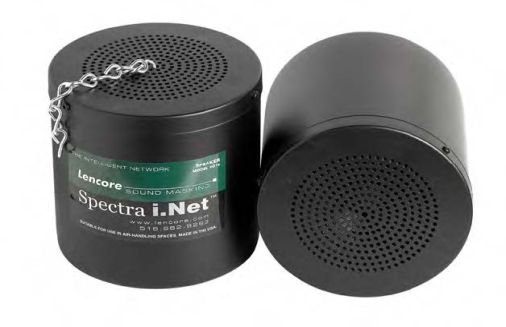
Generally, sound masking speakers are installed in the plenum, the space above the ceiling and below the roof, where they remain out of sight. They fill the plenum with sound which then filters down through the acoustical ceiling tile, providing a uniform and broad coverage. For spaces that forego ceiling tiles and opt for a more exposed style, there are also decorative speakers that can be installed on the ceiling, walls, or even desktops and match the décor and color of the space.
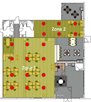
For mixed use spaces, sound masking systems may be designed into zones with the ability to designate zones which can be controlled independently from each other. Open office areas can be set to turn on and off at certain times of day or raise and lower the level of masking automatically depending on busy times, whereas private offices can be set to a separate zone that remains at the same level at all times.
The exact spacing of the speakers depends on a number of factors, including the height of the plenum, the height of the ceiling, as well as the thickness of the ceiling tile.
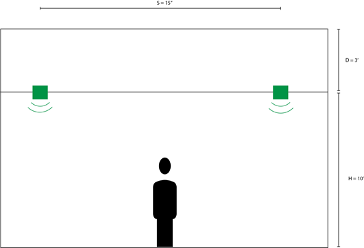
A commonly-accepted design criteria for sound masking speaker spacing is as follows: S=1.4*(2D+H-4). In many office spaces, this equates to approximately 15 ft apart, as they generally cover 225 square feet each. They are spaced at approximately 7 feet from the nearest wall, and spacing must be adjusted for the length and width of the room, as well as any irregular jut-outs or shapes.
This suggests that the on-center spacing (S) between speakers is governed by the ceiling height (H) and the plenum depth (D). This equation works well in large, open floor plans where the width of the room (W) is much greater than speaker spacing (S). However, speakers closest to the wall should be placed at S/2 from the wall.
NOTE: if cost constraints make the system price prohibitive, spacing may be increased to 1.7 *(2D+H-4). Likewise, offices that are less than 225 square feet with walls do not go to deck may “share” speakers with adjacent offices by placing the speakers over the demising partition. NOTE: In other cases, where spray insulation is used on the under-side of the deck, or there are structural cross-members limiting lateral sound movement, the speakers may need to be placed closer together.